
Quick Answer
A reliable wireless DMX setup starts with a documented signal path, not a last-minute pairing session. Divide the venue into zones, match the transmitter and receivers by supported protocol, record each universe, address, and channel mode, then test from the transmitter’s final position. If control becomes unstable, check power, pairing, patch, obstructions, and radio conditions in that order, with a fixture-supported fallback ready.
| Before the Event | During Setup | If Signal Fails |
|---|---|---|
| Map zones, confirm protocol and prepare the patch. | Place the transmitter, pair a small group, then expand. | Hold the approved look, isolate the failed path and use the documented fallback. |
| Record addresses, modes, battery targets and backup control. | Test scenes, audience conditions and a power restart. | Check power, link status, address, mode and new obstructions before re-pairing. |
Table of Contents
- Start With a Signal Plan, Not With Pairing
- Map the DMX Signal Path
- Where to Position the Wireless DMX Transmitter
- Pairing and Addressing Workflow
- How to Organize Multiple Lighting Zones
- Wireless DMX Troubleshooting Table
- Interference and Coexistence
- Build a Fallback Plan
- Pre-Show Test Checklist
- After-Event Reset and Documentation
- Frequently Asked Questions
Start With a Signal Plan, Not With Pairing
Divide the venue by control needs, physical separation, and recovery options. An entrance may hold one look while a ballroom follows the cue stack and a stage needs live changes. Treat an outdoor façade separately when access, weather exposure, or fallback differs from the indoor system.
For each zone, name the controller or console, DMX universe, transmitter, receiver-equipped fixtures, and backup method. Confirm that the transmitter and receivers use the same documented protocol and supported mode. If that compatibility work is not complete, use the wireless DMX compatibility guide before building the show file.
Last-minute pairing often fails because fixtures retain an old link, modes differ, addresses overlap, or the transmitter moves after testing. A one-page signal plan exposes those mismatches early.
Map the DMX Signal Path
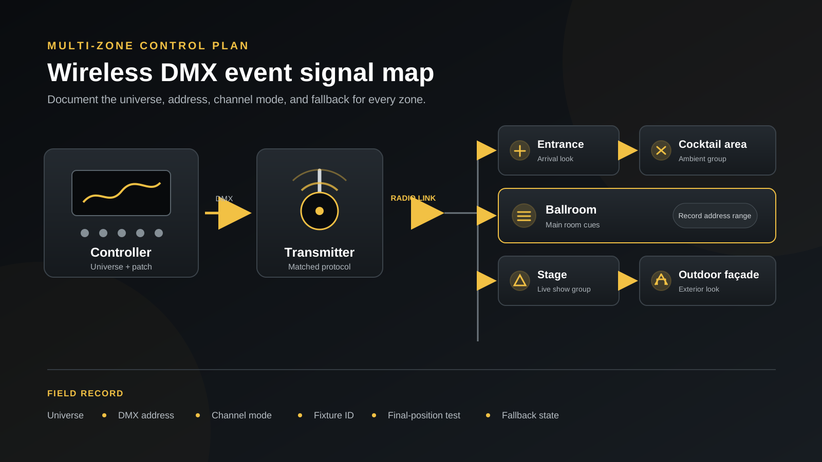
Write the path as controller → transmitter → wireless receivers → fixtures. Then label every logical handoff:
- Universe: the data set selected at the controller output.
- DMX address: the starting slot for each fixture or matched group.
- Channel mode: the channel count and attribute order matched by the console patch.
- Wireless system: the named protocol, mode, transmitter, and receiver role.
The diagram above branches one planned path to five zones. It shows control organization, not a promised radio range. Use the exact system’s documented topology and universe limits.
The ESTA Recommended Practice for DMX512 explains DMX512-A networks, address settings, wireless transport, and fault finding. For current formal references, check the ESTA published entertainment technology standards. Keep the radio link separate from the patch: a receiver can show a valid wireless link while the fixture still has the wrong address or channel mode.
Where to Position the Wireless DMX Transmitter
Place the transmitter where its antenna has the clearest practical path to receiver zones. A raised position can reduce blockage, but height does not guarantee a better link. Protect the transmitter, cables, power supply, and antenna from impact or handling.
Avoid metal cabinets, dense truss, LED-wall structure, large metal scenery, and stacked cases. People can alter a path that worked in an empty room, so retest after seating, staging, and equipment are in place. Use the manufacturer’s antenna orientation.
The best wireless DMX transmitter placement depends on the venue, protocol, antennas, receivers, radio environment, and manufacturer instructions. Never turn an open-field figure into a universal on-site distance. Outdoors, protect each device and connection to its own rating. Fixture IP65 does not cover an open connector, uncovered charging point, charger, transmitter, or damp charging operation.
Pairing and Addressing Workflow
Use the fixture and transmitter instructions for button sequences and indicator meanings.
- Clear old pairing where the manual allows it. Unlink previous transmitters so a stored association does not create a false fault.
- Confirm the protocol and transmitter. Match the receiver system, mode, radio role, and firmware requirements.
- Connect a small test group. Start with two or three fixtures and confirm their link indication and response.
- Set the DMX address. Assign each fixture or intentional group a known start; prevent unintended overlaps.
- Confirm the channel mode. Match the fixture’s selected mode to the console personality and channel footprint.
- Expand one zone at a time. Move fixtures to final positions and test each zone before starting the next.
- Record the configuration. Save the universe, address, mode, fixture ID, transmitter, zone, and fallback.
Do not repeatedly clear and re-pair the entire system when one unit fails. First compare that unit’s power, link indicator, address, mode, firmware, and position with a working neighbor.
How to Organize Multiple Lighting Zones
Zones should reflect cueing and recovery. Fixtures may share an address only when they should mirror; independent fixtures need separate, non-overlapping footprints. This is a template, not a universal allocation.
| Zone | Address range to record | Control group | Backup status |
|---|---|---|---|
| Entrance | Universe ___, start ___ to end ___ | Arrival look | Static look saved and locally accessible |
| Cocktail area | Universe ___, start ___ to end ___ | Ambient group | Preset confirmed on assigned fixtures |
| Ballroom | Universe ___, start ___ to end ___ | Main room cues | Wired route or approved hold look documented |
| Stage | Universe ___, start ___ to end ___ | Live show group | Priority recovery method rehearsed |
| Outdoor façade | Universe ___, start ___ to end ___ | Exterior look | Weather-safe local state and access plan confirmed |
One transmitter may serve multiple zones only when the system documentation, universe plan, receiver count or topology, and venue test support it. A separate transmitter or universe can isolate a critical zone, but adding radios without a plan can also complicate troubleshooting.
Wireless DMX Troubleshooting Table
Work from power and configuration toward radio conditions. Change one variable at a time and keep a known-good fixture available for comparison.
| Symptom | Likely cause | What to check | Fallback |
|---|---|---|---|
| Fixtures do not respond at all | Controller output, transmitter input, protocol, pairing, or power is missing | Verify universe output, transmitter TX state, protocol, receiver link, battery, address, and mode | Use the approved local look or tested wired path if supported |
| Only some fixtures respond | Affected units have stale pairing, different mode, wrong address, low battery, or blockage | Compare a failed unit with a working neighbor: link, firmware, address, mode, battery, antenna, and position | Hold working groups; set accessible failed fixtures to the approved local state |
| Fixtures drop out intermittently | Obstruction, marginal placement, unstable power, or changing radio conditions | Watch link and battery indicators; inspect new metal, LED-wall, truss, cabinet, or audience blockage; test an approved transmitter position | Use the rehearsed static look or wired control for that zone |
| Addresses are correct but colors differ | Fixture channel modes, console personalities, calibration, color systems, or dimmer attributes do not match | Compare selected mode and channel order, then test dimmer and each color attribute at known values | Use a simple matched static color that has been checked on every fixture |
| Control is wrong after changing channel mode | The fixture footprint changed but the console patch or following addresses did not | Repatch the exact personality, recalculate non-overlapping footprints, and confirm every affected starting address | Return to the last documented mode and patch if the show file supports it |
| Fixtures will not reconnect after a restart | Stored-link behavior, boot order, transmitter state, or reset settings changed | Follow the startup sequence; check transmitter mode, receiver memory, firmware, and link before clearing pairing | Start the approved preset, then recover one zone at a time |
| Outdoor signal becomes worse | Structures, vehicles, people, moisture exposure, or transmitter placement changed | Inspect the path; ensure covers and connectors are closed and dry; retest from a protected approved position | Use a weather-suitable local look or supported protected wired route |
| Wireless works but batteries end early | Brightness, active channels, receiver operation, temperature, battery condition, or setup time exceeded the test | Compare real scenes and powered time with the runtime test; check batteries and remove abnormal units | Use approved lower output, rotate charged fixtures, or use the planned powered alternative |
Interference and Coexistence
Many wireless DMX products share the 2.4 GHz environment with Wi-Fi, Bluetooth, intercoms, and control tablets. Wi-Fi does not automatically break wireless DMX; systems use different radio management and recovery methods.
List the show’s radios and transmitter locations. Test with the LED wall, network hardware, cameras, intercoms, and audience devices present when possible. Follow the wireless manufacturer’s coexistence, firmware, and antenna guidance.
The LumenRadio overview of CRMX wireless DMX is an example of a named technology ecosystem; it does not make every 2.4 GHz fixture compatible with CRMX. Protocol confirmation comes before wireless DMX troubleshooting.
Build a Fallback Plan
A fallback should preserve an acceptable look, not every live cue. Use only methods confirmed for the exact fixture:
- Wired DMX: pre-plan cable, splitter, termination, access, and source-priority behavior.
- Manual static color: record the approved color and dimmer values plus who can reach each fixture.
- Local preset: store and test a scene that remains useful without a live radio link.
- IR control: keep a compatible remote available only when the fixture documents IR and access conditions make it practical.
- Spare transmitter: match protocol, mode, firmware, power, cabling, and saved configuration before show day.
The Flex PL18 Pro control specifications list wired DMX512, 2.4GHz wireless DMX512, 2/6/8/11-channel modes, an infrared remote, a Wi-Fi app, master-slave operation and automatic programs. Test the required functions and fallback behavior with the exact fixtures and transmitter before including the model in a wireless plan.
Pre-Show Test Checklist
- [ ] Pair every receiver to the intended transmitter and confirm the documented link state.
- [ ] Compare every fixture address with the show patch.
- [ ] Match every channel mode and console personality.
- [ ] Run each required scene, color, dimmer level, and transition by zone.
- [ ] Record battery state and confirm runtime against the real show schedule.
- [ ] Activate the supported backup control and return to normal control.
- [ ] Interrupt the wireless signal in a controlled test and confirm the expected fixture behavior.
- [ ] Power-cycle the controller, transmitter, and representative fixtures using the documented sequence.
- [ ] Repeat critical tests from final positions with staging, technical equipment, and normal room occupancy represented.
After-Event Reset and Documentation
Before packing, record the final universe, address, mode, zone, transmitter, fixture ID, battery, and irregular behavior. Note where signal loss occurred and what restored it.
Clear links that should not enter the next kit, but retain pairing when the plan requires it. Quarantine abnormal batteries, damaged antennas, wet or open connectors, and repeat faults. Update the setup sheet so the next event does not inherit undocumented settings.
Frequently Asked Questions
Why does wireless DMX work on some fixtures but not others?
Check pairing, protocol mode, firmware, address, channel mode, battery, antenna, and obstruction. Compare one failed fixture with a working unit; a valid receiver link does not prove the console patch matches.
Should the transmitter be placed high above the audience?
Height can reduce blockage but is not a guarantee. Use a protected position with a clear path, correct antenna orientation, safe cabling, and manufacturer-approved placement; retest with the room occupied.
Can multiple zones share one transmitter?
Yes, if the system supports the universe, receivers, and topology, and the venue test passes. Keep zones separated in the patch; critical or isolated zones may need a different path.
What causes intermittent wireless DMX signal loss?
Common causes include changing obstructions, transmitter placement, antenna orientation, power, local radio activity, settings, and damage. Observe link and power indicators during the fault and compare with a known-good unit.
Should every fixture use the same DMX mode?
Not necessarily. Different documented modes can work when patch and footprints match. A shared mode simplifies a mirrored group. Update the patch and following addresses after every mode change.
What is the safest fallback if wireless control fails?
Use the method supported by the fixture, rehearsed by the crew, and acceptable for the event: wired DMX, local color, preset, IR, or a matched spare transmitter. Never infer it from another model.
Can wireless DMX be tested before arriving at the venue?
Yes. Bench-test protocol, pairing, addresses, modes, scenes, restart behavior, batteries, and fallback. Because the venue adds structures, radios, audience, and equipment, repeat the test from final positions.
Make the Recovery Path as Clear as the Control Path
A practical wireless DMX setup gives every zone a named signal path, documented patch, final-position test, and model-supported fallback. That preparation turns signal loss from a show-wide mystery into a limited problem the crew can isolate.